One long lunch after
2026-11-01 · Electronics/RF Clock
Last time[1] I had to stop on the filter design because lunch got in the way. And then many other things (read: other projects at more exciting stages) got in the way. But finally I am back, and actually some progress has been made in the meantime.
Let's start with the exciting part - the first filter is actually ready!
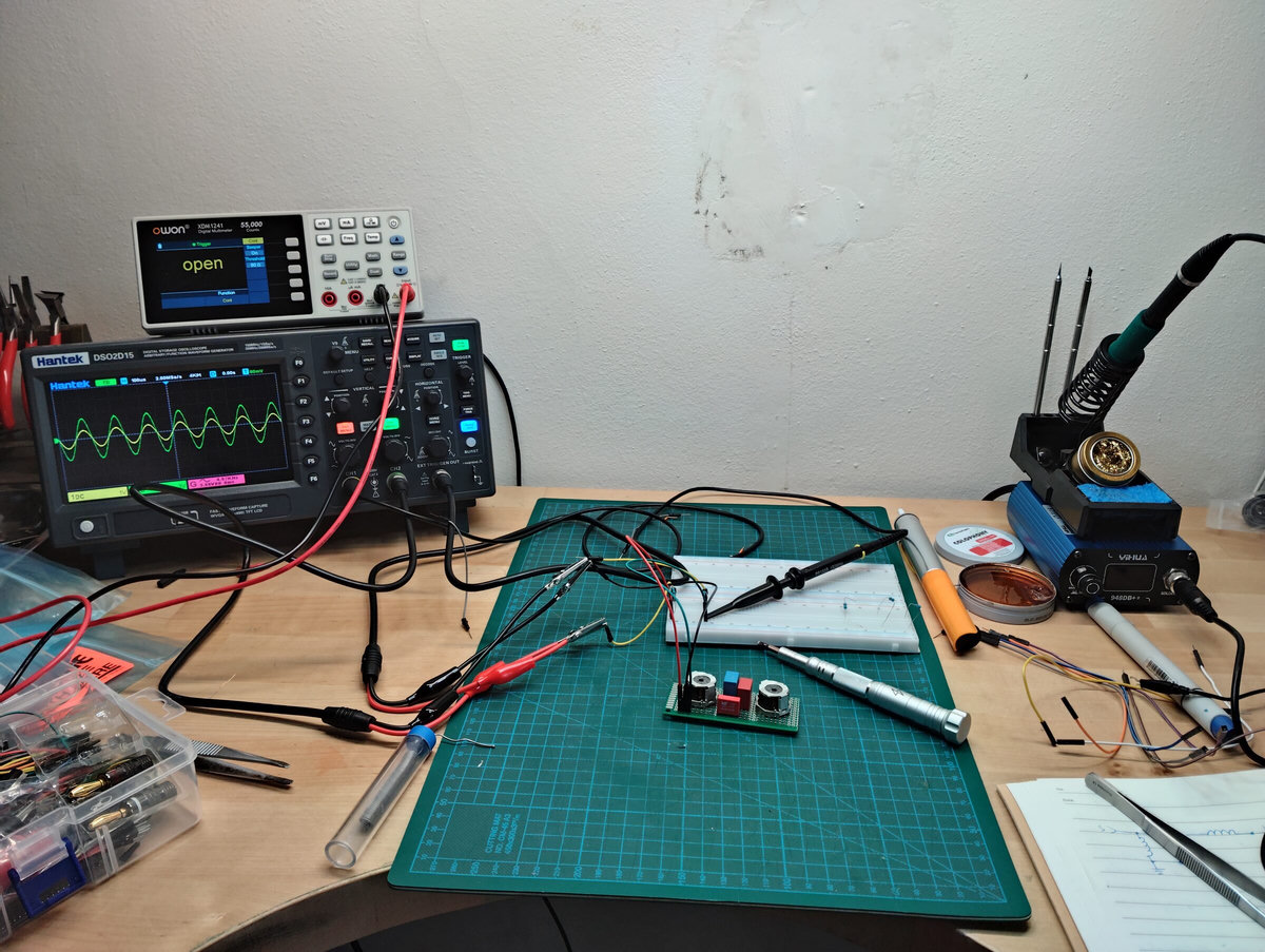
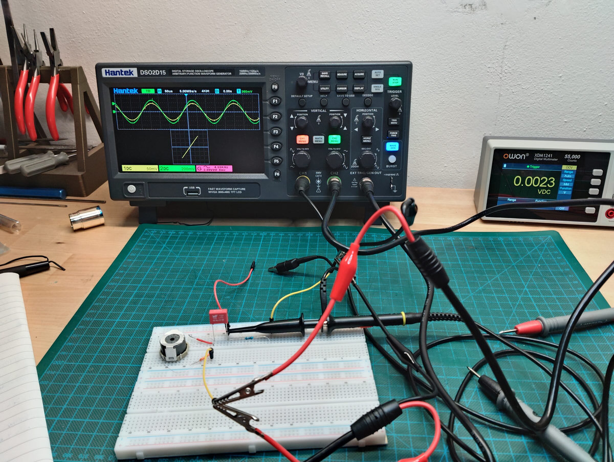
I even tried to characterize it:
| f1/Th kHz | f2/Th kHz | |
|---|---|---|
| f-3dB | 4.18/4.22 | 5.01/4.96 |
| f-10dB | 3.89/3.97 | 5.38/5.26 |
| f-15dB | 3.65 | 5.62/5.52 |
where /Th are my theoretical values, based on all those guesses from the filter design table. The -20dB level was not calculated at all, since with 2 poles there is no chance to stay out of the neighbouring bands. The lower -15dB /Th is missing because there is nothing below, so the task was just to measure what the real filter gives.
There is a loss of 7dB at fC, mostly due to my Rin/out of 510Ω (the divider alone eats 6dB), so this was set as the reference point.
Results are kinda not too bad, but not thrilling either - things, of course, turned out worse in ferrite than on paper:
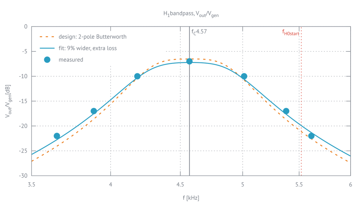
That's a very brave approximation from the 7 points I measured!
But at least the central frequency fC=4.57 kHz is obviously on point, because I was the one responsible for winding the pots and tuning them (got the ferrite slugs too, in all the colours available 🤣). The generator on this Hantek is good enough and has fine tuning. XY mode is also there, so tuning the poles and the whole filter was very easy. The only hard part was when I forgot to ground the load resistor and spent an hour debugging why the already tuned filter stopped working. 🤫
Not going to lie, it was fun turning all these knobs on the Hantek and watching the colourful buttons glow at night 🤓. What turned out to be not so exciting is its precision... Now, if somehow someone actually reads this, don't take it as a review - this is literally my first experience with any oscilloscope - but! Its math functions seem to be kinda on the suggestive side of things. The FFT resolution is not useful, and I couldn't find a way to measure attenuation directly, so I ended up measuring peaks (Vtop) on both waves and then tuning to the target ratio (-3, -10, -15 dB) manually. Needless to say, this is annoying, and the resolution on Vtop seems to be wired to the current channel's V/div, so it needs to be cranked up to get any decent readings. Past -15dB this is mostly in the "treat what I display as a suggestion" department.
Anyway, if we reconstruct fC from the measured values:
| √(f1f2) kHz | |
|---|---|
| -3dB | 4.58 |
| -10dB | 4.57 |
| -15dB | 4.53 |
So, not terrible. I am surprised how close that tiny table from PEFI[2] can land you. Whether the current -15dB point is enough or not - I have no idea! Clearly it landed in the next channel, and I would need a couple of extra dB to get out of it. My plan is to get H0 built and start figuring out the Frequency-to-Voltage (F/V) part. That will require some semiconductors, which is my next stop. So far I have only studied AC/DC circuit analysis and, clearly, got into some basics of filter design. Then I'll know if this is a clock or a random number display.
So there is definitely going to be a gap until I come up with the next part, as there is a lot of theory to go through. At least I hope the itch to jump straight into Handbook of Filter Synthesis[3] is behind me, till another project!
The current progress sits at filter design 2.
-
My previous post on the subject - A decadent band plan ↩
-
Paul Scherz and Simon Monk, Practical Electronics for Inventors, 4th ed. (McGraw-Hill, 2016). ↩
-
Anatol I. Zverev, Handbook of Filter Synthesis (John Wiley & Sons, 1967). ↩